

GENERAL INFO
There are 5 gas zones reservoir inside 9 5/8” casing sections that will be completed with MST single trip multi-zone sand control which is equipped with single selective production equipment. All GP zones will be treated either with HRWP or circulation pack treatment. The pumping services will be performed by utilizing pumping skids on the rig.
For main zone target in the 4 ½” liner section will not require any sand control method, the perforation will be carried out in the future operation.
Once lower completion is completed, the operations will be continued with run-in hole the upper completion with 4 ½” production tubing, and completion sub-assemblies as per the proposed completion schematic.
WELL STATUS PRIOR TO COMPLETION
- Fluid inside 4 ½” Liner: 1.09 SG KCl Brine.
- Fluid inside 9 5/8” Production Casing: 1.09 SG KCl Brine.
- 9 5/8” production casing has been tested to 6,200 psi with 1.18 SG NABM on 16/3/2013 (green cement test).
- 9 5/8” production casing + 4 ½” liner tested to 2,500 psi with 1.39 SG LT-OBM on xx/xx/2013 (green cement test).
- Formation content: Gas.
- No open perforations (well in closed system).
WELL INFORMATION
- Depth Measurement Unit : Meter
- Rig Floor Elevation : 34.22m above MSL
- Water Depth : 48.58m below MSL
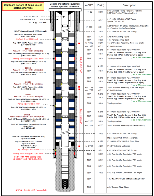
- Completion Type : 9 5/8” MST – Gas Producer
- TD : ± 4426 mMD / 3591 mTVD
CASING AND CEMENTING CONFIGURATION
| Casing | Shoe Depth TMD (m) | Cementing |
| 36” | 174.0 | Driven |
| 13-3/8” K-55 68# BTC | 1222.46 | To Surface |
| 9-5/8” 53.5# TMS-28 P110 | 3460.67 | To ± 1020 mMD |
| 4-1/2” 13.5# VTNE L80 | 4426 | To top liner |
FLUID DATA
- Completion Fluid : 1.09 SG Filtered KCl Brine
- Packer Fluid : 1.09 SG Filtered KCl Brine + Corrosion Inhibitor
- Pre-HRWP Fluid Loss Pill : HEC Pill with Liquid Vis-EP (80# eq.), 1.09 SG KCl Base Fluid (no breaker)
- HRWP/GP Carrier Fluid : HEC Linear Gel 30#, 1.09 SG KCl Base Fluid
- Workstring Pickle Fluid : 7.5% HCl Acid
- Note #1: Brine (completion fluid, base fluid for gel, etc.) shall be filtered to 2 microns absolute.
- Note #2: Crosslinked HEC 100# is a crosslinked fluid loss pill that requires acid to break viscosity. The crosslinked HEC should be used in case of extreme losses.
RESERVOIR OBJECTIVES AND BRINE WEIGHT REQUIREMENT
There are 5 zones to be completed using 9-5/8” MST Gravel Pack Assembly and stimulated with High Rate Water Pack (HRWP) as the base case or circulation pack. Find the reservoir properties below.
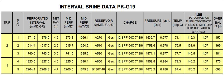
*all depths are referred to 12-1/4” section Completion Log
Below is the proposed completion schematic.
WELLBORE CLEANING OBJECTIVES
Once the well is drilled to TD and cemented, the well should be displaced to a clean, solids-free completion fluid before commencing with the completion. During the transition from drilling mud to completion fluid, the fate of the well is very often determined since it is estimated that a third of all failed completions are due to poor debris management. Regardless of the completion method, all displacements are designed to achieve the following:
- Remove the drilling mud from the wellbore, and ensure that the casing, riser, and/or open hole are free of drilling mud residue
- Minimize fluid interface and associated waste during the transition from drilling mud to completion fluid (i.e. minimize disposal costs)
- Reduce non-productive time (i.e. rig time)
- Reduce filtration time
- Maximize well productivity
- Perform the operation with high QHSE standards
To achieve these objectives, all displacements must consider the two essential elements of wellbore cleaning: mechanical cleaning and chemical cleaning. Regardless of the mud system or completion method, both elements are critically important and therefore must be considered.
MECHANICAL WELLBORE CLEANING
It is important to understand the client’s objectives when designing a mechanical wellbore cleaning string. Mechanical wellbore cleaning tools (MWCT) are designed to work in a single trip.
This means that multiple operations can be performed using a single clean-up string. This flexibility provides the client with significant cost savings and dramatically reduces the number of trips (i.e. cuts down on rig time). Some simultaneous operations are:
- Drift the casing, ensuring that the lower completion can be run without problems
- Clean the liner top so that debris does not fall back into the producing zone
- Jet the BOP and collect any dislodged debris, thus keeping it from going downhole
- Boost the annulus to ensure that solids and debris flow back to the surface
- Scrape the casing (including all packer set points) to remove scale and mud solids
- Scrape the casing and catch ferrous debris after the perforation process
- Brush and clean the riser to remove debris
- Filter the downhole fluid while pulling out of hole (POOH), thus validating the displacement
These are just a few operations that can be performed using a single wellbore clean-up string. Additional operations may be performed as required by the client.
4-1/2” LINER CLEAN-OUT TRIP
Perform 4 ½” liner clean out with following configuration.
| ▫ | 3-1/2” bit or 3-5/8” mill | – 2-3/8” Reg Pin up | |
| ▫ | 2-7/8” Motor | – 2-3/8” Reg Box x Pin | |
| ▫ | X/O | – 2-3/8” Reg Pin x Pin | |
| ▫ | Float Sub | – 2-3/8” Reg Box x 2-3/8” IF Box | |
| ▫ | X/O | – 2-3/8” IF Pin x 2-3/8” HT Pac Box | |
| ▫ | 2-3/8” Jar | – 2-3/8” HT Pac Pin x 2-3/8” HT Pac Box | |
| ▫ | X/O | – 2-3/8” HT Pac Pin x 2-7/8” HT Pac Box | |
| ▫ | TBA jts 2-7/8” HT Pac DP | – 2-7/8” HT Pac Pin x Box | |
| ▫ | X/O | – 2-7/8” HT Pac Pin x NC50 Box | |
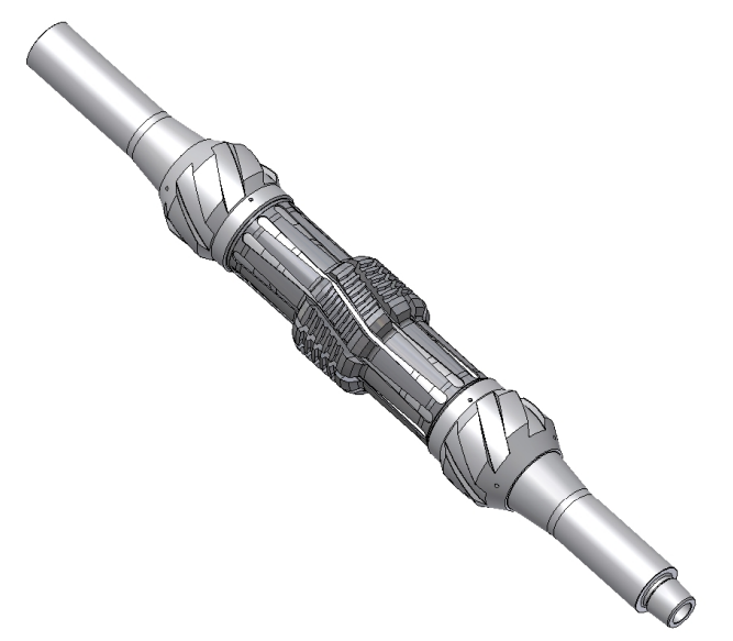
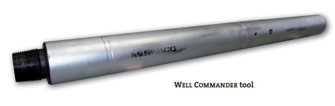
| ▫ | 7” OD CIRCULATING SUB/VALVE | – NC50 Pin x Box | |
| ▫ | X/O | – NC50 Pin x 5” GPDS-50 Box | |
| ▫ | 1 jt 5” GPDS-50 Workstring | – GPDS-50 Pin x Box | |
| ▫ | TBA jts 5” GPDS-50 HWDP | – GPDS-50 Pin x Box | |
| ▫ | TBA jts GPDS-50 Workstring | – GPDS-50 Pin x Box |
Note:
All tubular to be drifted and flush with seawater while pick up.
Test circulating sub at surface.
- Continue RIH 4-½” liner clean out assembly.
Note: break circulation every 15 joints picked-up while running 2-7/8” DP to avoid pulling motor.
- Fill-up string as required and break circulation every 300 m while running mill inside 4-1/2” liner.
- Wash down on last stand and tag landing collar.
- Circulate string volume with mud at maximum flow rate as recommended.
- Pump HiVis Pill followed by brine or sea water as per procedure in order to fill ½ liner volume.
Note: the density of brine will be adjusted in order to maintain overbalance hydrostatic pressure over higher reservoir pressure with mud in the 9-5/8” casing and brine in the liner.
- Drop 1 x 2” activation ball to activate the circulating sub as per instruction.
- Close Annular BOP and pump HiVis Pill and continue displacing oil base mud inside 9-⅝” casing at 800 lpm with sea water maintaining counter pressure in order to maintain minimum 30 bars overbalance pressure over higher reservoir pressure.
- Bleed-off pressure by steps of 10 bars to prove liner integrity. Any sign of influx replace sea water by mud maintaining minimum 30 bars overbalance pressure over higher reservoir pressure.
- Open well to flow check for 1 hour
Note: Horner plot to be filled up.
- Circulate sea water at 2500 lpm until clean return at surface. Dump returns.
- Drop 2 x 1-⅜” steel ball to deactivate the circulating sub as per instruction.
- Circulate sea water across liner and perform regular flow check until sea water reach top of liner. Then complete bottom up.
- Spot 1.09 SG KCl filtered brine across liner with enough excess to compensate 2-7/8 DP volume displacement while pulling out.
- Perform minimum ½ hour flow check (or until flow check stable).
- POOH and L/D 2-7/8 DP and Liner Clean-out BHA.
Note: F&C to define pills strategy and clean-out sequence.
WELLHEAD AND BOP/RISER CLEANING #1 AND CASING SCRAPER RUN
9-5/8” CASING SCRAPER AND CLEAN-OUT TRIP
- P/U and M/U Casing Scraper Assembly, consists of (from bottom to top):
| ▫ | 6” Bit (nozzle less) | – 3 ½” Regular Pin Up (Baker) | ||
| ▫ | Bit Sub | – 3 ½” Regular Box x 3 ½” IF Box | ||
| ▫ | 9 ⅝” Ferrous Debris Catcher tool | – 4 ½” IF Box x Pin | ||
| ▫ | 9 ⅝” Casing Scraper tool | – 4 ½” IF Box x Pin | ||
| ▫ | 9 ⅝” Ferrous Debris Catcher tool | – 4 ½” IF Box x Pin | ||
| ▫ | 9 ⅝” Casing Brush tool | – 4 ½” IF Box x Pin | ||
| ▫ | X/O | – 4 ½” IF Box x 5” GPDS-50 Pin | ||
| ▫ | 5” GPDS-50 Workstring | – GPDS-50 Pin x Box | ||
| ▫ | TBA 5” HWDP | – 4 ½” IF Box x 4 ½” IF Pin |
Note:
▫ Use stands of HWDP since the beginning in 9-5/8” casing section to ensure cleanliness of HWDP. Those HWDPs are needed for TCP trip and GP deployment both trips.
- RIH wellbore cleanout assembly with 5” GPDS-50 workstring
- Scrap all proposed packer setting depth three (3) times as per depth interval given by Completion
Supervisor on board. - Continue RIH as per tally to tag top of 4-½” liner with maximum 3 tons set-down weight.
- P/U 2 meter above PBR and connect string to TDS. Record P/U and S/O weight.
- Perform displacement of wellbore fluid through the workstring using cement unit and mud pump as
required as per following procedure : Rotate the string at 15 – 20 RPM and reciprocate 1 stand during wellbore clean-out. Pump 5 m3 of hivis pill and displace with sea water at maximum rate for 1 casing volume. Divert to wash train to choke manifold, pump through the string at maximum rate for 1 casing volume. Repeat this procedure if necessary. Displace with sea water until clean return is observed. Stop rotating and reciprocating, displace sea water with 1.09 SG filtered KCl brine until SGin = SGout, NTU < 50 and TSS < 0.01%.
- Disconnect TIW and cement unit, POOH and L/D wellbore cleanout tools Assembly.
- Collect and weigh any trapped debris at shakers and ferrous debris catcher tools.
- Perform pressure test of 9-5/8” and 4-1/2” liner to 4,500 psi for 10 minutes using 1.09 KCl brine by closing shear/blind rams and pump through lower kill line.
WELLHEAD AND BOP/RISER CLEANING #1
- Retrieve wear bushing.
Note:
Measure tubing hanger landing point to the rotary table (RTE).
- P/U and M/U Wellhead Jetting tool, connect to TDS.
- Jetting the wellhead area using seawater at 12 bpm or maximum pressure 1,000 psi for 15 minutes using rig pump. Dump return overboard. Meanwhile, cement unit to pump seawater (10 bpm minimum) through emergency kill line and take the return to shaker and dump overboard. Note: DO NOT JET BOP CAVITIES.
- POOH and L/D Wellhead Jetting Tool.
- P/U and M/U BOP Jetting Sub Assembly, consists of (from bottom to top):
| ▫ | 6-1/2” Bull Nose Sub | – 4-1/2” IF Box |
| ▫ | 9-5/8” BOP Riser Junk Catcher | – 3-1/2” IF Box x 4-1/2” IF Pin |
| ▫ | X-over Sub | – 4-1/2” IF Box x 3-1/2” IF Pin |
| ▫ | 1 stand of 5” GPDS-50 | – 4-1/2” IF Box x Pin |
| ▫ | 9” OD Ferrous Debris Catcher tool | – 4-1/2” IF Box x Pin |
| ▫ | 1 stand of 5” GPDS-50 | – 4-1/2” IF Box x Pin |
| ▫ | 12” BOP Jetting Wash Tool | – 4-1/2” IF Box x Pin |
| ▫ | 5” GPDS-50 | – 4-1/2” IF Box x Pin |
Note:
▫ Apply minimum dope on pin end only with paintbrush for workstring. Wipe excess dope from outside after making up the string. This must be done throughout the job.
▫ Ensure the 5” GPDS-50 used is clean and drifted.
▫ Space-out to ensure junk basket is always in the 9-5/8” casing when reciprocating across the jetting interval.
- Connect BOP Jetting Sub to TDS and lower down 1 meter below rotary table, check the jetting action by pumping down the string.
- RIH BOP Jetting Sub to have 5” GPDS-50 workstring across BOP rams and junk basket is inside 9-5/8” casing.
- Cycle close and open all BOP rams except SHEAR/BLIND RAMS to dislodge any trapped debris.
- RIH Jetting Sub to bottom of BOP as low as possible.
- Start pumping down the string with rig pump using seawater at 6 bpm or 1,000 psi maximum. Move ported jetting sub up and down and rotate at 30 RPM (reciprocate the jetting sub across BOP and Riser) for 5 passes. Keep pumping until a clean return is observed.
Note: take return through shakers and dump overboard.
- Before POOH, pump 3 m3 hivis pill using cement unit through emergency kill line at 3 bpm.
- After 3 m3 hivis pill pumped, continued by pumping seawater through TDS at maximum flow rate with maximum pressure 2,000 psi until the return is clean. Stop jetting.
- Disconnect TDS, POOH, and L/D BOP Jetting Sub.
- Collect and weigh any trapped debris on magnets and in a junk basket.
- Install tester plug.
- Function test Shear/Blind Rams (3 times).
- Retrieve tester plug, visual check for any debris, and re-install back wear bushing.
PERFORATIONS DEBURRING #1 AND BOP/RISER CLEANING #2
This phase is post perforation on zone #3 and #4.
PERFORATIONS DEBURRING #1
- M/U Deburring tools Assembly, consist of (from bottom to top):
| ▫ | 4-1/2” Locator Seal w/ Half Muleshoe | – 4-1/2” IF Box |
| ▫ | 9-5/8” Ferrous Debris Catcher tool | – 4-1/2” IF Box X Pin |
| ▫ | 8.375” Steering Mill | – 4-1/2” IF Box X Pin |
| ▫ | 9-5/8” Ferrous Debris Catcher tool | – 4-1/2” IF Box X Pin |
| ▫ | 8.375” Steering Mill | – 4-1/2” IF Box X Pin |
| ▫ | 5” GPDS-50 | – 4-1/2” IF Box X Pin |
Note:
▫ Ensure maximum OD assembly that will pass through Sump Packer Assembly is less than 6” OD.
- RIH Deburring tools Assembly at 1.5 minutes/stand.
Note:
▫ Apply minimum dope on pin end only with paintbrush for string. Wipe excess dope from outside after making up the string. This must be done throughout the job.
▫ Move Deburring tools Assembly up and down slowly to avoid swabbing the formation.
- Continue RIH until 1 stand prior to steering mill reaches the uppermost perforation on the 1st trip at 1823.5 mGR (zone #4), record P/U and S/O weight.
- Continue down and deburr 2 times down and 1 time up for all perforation intervals (order from the top). Whenever the BHA connection permits rotation, rotate workstring at 15-30 RPM during deburring.
- Stop rotating once finish at one zone and continue RIH to the next perforation intervals and repeat the same deburring process.
- Watch the torque reading.
- The assembly will not be able to deburr the bottom-most perforation interval due to the distance from the bottom-most perforation to the top of the Sump Packer is only 5 meters.
- Maximum depth of Locator Seal Assembly during rotation is 2-3m above the sump packer.
- Continue RIH slowly to tag top of Sump Packer at 2286 mGR with 2 tons maximum set down weight. Record tag depth for reference and compare with electric line and TCP depth. P/U Deburring tools Assembly until 6” Bullnose position is 2 meters above top of Sump Packer.
- Connect TDS, do break circulation by pumping at the minimum rate 2 bpm higher than losses rate until the return is on the surface.
- Pump 5 m3 hivis pill and displace directly with 1.09 SG filtered KCl brine.
- Continue displace at 8 bpm and/or maximum 1,000 psi on the workstring until hivis pill on the surface and clean return is observed.
- RIH back slowly and tag Sump Packer with 2 tons maximum set down weigh until seal assembly sting into and land the no-go locator inside Sump Packer. Record and compare to the previous tag depth.
- Slack-off to 10 tons and pressure-up string to test Sump Packer seal bore to 1,000 psi for 5 minutes using rig pump. Bleed-off pressure to 0 psi.
- Disconnect TDS, and POOH 1 stand of Deburring tools Assembly until seal assembly stings out from the seal bore of Sump Packer. Check the static losses, if losses are more than 3 m3/hr spot 5 m3 of hivis pill to the hole.
- POOH Deburring tools Assembly slowly at 1.5 minutes/stand to avoid swabbing the formation.
- L/D Deburring tools Assembly, collect, and weigh the debris on ferrous debris catcher tools.
BOP/RISER CLEANING #2
- P/U and M/U BOP Jetting Sub Assembly.
- Connect BOP Jetting Sub to TDS and lower down 1 meter below rotary table, check the jetting action by pumping down the string.
- RIH BOP Jetting Sub to have 5” GPDS-50 workstring across BOP rams and junk basket is inside 9-5/8” casing.
- Cycle close and open all BOP rams except SHEAR/BLIND RAMS to dislodge any trapped debris.
- RIH Jetting Sub to bottom of BOP as low as possible.
- Start pumping down the string with rig pump using seawater at 6 bpm or 1,000 psi maximum. Move ported jetting sub up and down and rotate at 30 RPM (reciprocate the jetting sub across BOP and Riser) for 5 passes. Keep pumping until a clean return is observed.
- Before POOH, pump 3 m3 hivis pill using cement unit through emergency kill line at 3 bpm.
- After 3 m3 hivis pill pumped, continued by pumping seawater through TDS at maximum flow rate with maximum pressure 2,000 psi until the return is clean. Stop jetting.
- Disconnect TDS, POOH, and L/D Weatherford Jetting Sub.
- Collect and weigh any trapped debris on magnets and in a junk basket.
- Re-install back wear bushing.
2ND TRIP TCP PERFORATION (ZONE #3, ZONE #2 AND ZONE #1)
PERFORATIONS DEBURRING #2 AND BOP/RISER CLEANING #3
PERFORATIONS DEBURRING #2
- M/U Deburring tools Assembly same as the assembly run on the 1st trip.
- RIH Deburring tools Assembly at 1.5 minutes/stand.
- Continue RIH until 1 stand prior to steering mill reaches tuppermostost perforation on the 2nd trip at 1371.5 mGR (zone #1), record P/U and S/O weight.
- Continue down and deburr 2 times down and 1 time up for all perforation intervals (order from the top). Whenever the BHA connection permits rotation, rotate the workstring at 15-30 RPM during deburring. Stop rotating once finish at one zone and continue RIH to the next perforation intervals and repeat the same deburring process.
- Continue RIH slowly to tag Top GP Packer 1st trip at 1744.12 mGR with 2 tons maximum set down weight. Record tag depth for reference and compare with electric line and TCP depth. P/U Deburring tools Assembly until 6” Bullnose position is 2 meters above top of Sump Packer.
- Connect TDS, do break circulation by pumping at the minimum rate 2 bpm higher than losses rate until the return is on the surface.
- Pump 5 m3 hivis pill and displace directly with 1.09 SG filtered KCl brine. Continue displace at 8 bpm and/or maximum 1,000 psi on the workstring until hivis pill on the surface and clean return is observed.
- RIH back slowly and tag Top GP Packer 1st trip with 2 tons maximum set down weight until seal assembly sting into and land the no-go locator inside the packer. Record and compare to the previous tag depth.
- Slack-off to 10 tons and pressure-up string to test Sump Packer seal bore to 1,000 psi for 5 minutes using rig pump. Bleed-off pressure to 0 psi.
- Disconnect TDS, and POOH 1 stand of Deburring tools Assembly until seal assembly stings out from the seal bore of the packer. Check the static losses, if losses are more than 3 m3/hr spot 5 m3 of hivis pill to the hole.
- POOH Deburring tools Assembly slowly at 1.5 minutes/stand to avoid swabbing the formation.
- L/D Deburring tools Assembly, collect and weigh the debris on ferrous debris catcher tools.
BOP/RISER CLEANING #3
- P/U and M/U BOP Jetting Sub Assembly
- Connect BOP Jetting Sub to TDS and lower down 1 meter below rotary table, check the jetting action by pumping down the string.
- RIH BOP Jetting Sub to have 5” GPDS-50 workstring across BOP rams and junk basket is inside 9-5/8” casing.
- Cycle close and open all BOP rams except SHEAR/BLIND RAMS to dislodge any trapped debris.
- RIH Jetting Sub to bottom of BOP as low as possible.
- Start pumping down the string with rig pump using seawater at 6 bpm or 1,000 psi maximum. Move ported jetting sub up and down and rotate at 30 RPM (reciprocate the jetting sub across BOP and Riser) for 5 passes. Keep pumping until a clean return is observed.
Note: take return through shakers and dump overboard.
- Before POOH, pump 3 m3 hivis pill using cement unit through emergency kill line at 3 bpm.
- After 3 m3 hivis pill pumped, continued by pumping sea water through TDS at maximum flow rate with maximum pressure 2,000 psi until the return is clean. Stop jetting.
- Disconnect TDS, POOH and L/D Jetting Sub.
- Collect and weight any trapped debris on magnets and in junk basket.
- Re-install back wear bushing.
We can add a junk catcher tool in the 9-5/8″ cleanout string or in any casing as per well schematic. De-burring tools assembly can use watermelon mills or string mill beside the original wellbore cleanout tools de-burring tools.